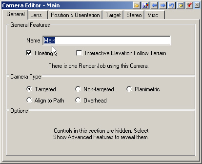
1. After data import is complete, save the project and go to the Render Task Mode. Open the YNP Camera and rename it Main.
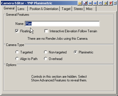
2. Use Edit Next on the editor titlebar to move to the YNP Planimetric camera and rename it Plan.
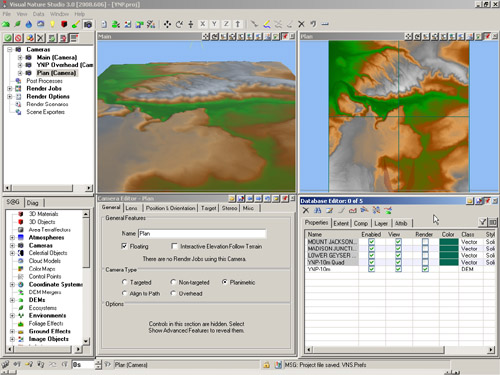
3. Open the Main view, Plan view, and Database Editor.
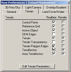
4. Open the Plan Camera View Preferences to the Terrain page and check the Terrain Polygon Edges box.
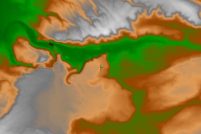
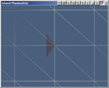
5. Use the + key or mouse scroll wheel to zoom into the wireframe representation of the 3D terrain surface. It’s a grid of regularly spaced georeferenced points, each with an elevation.
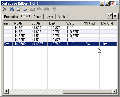
6. Go to the Database Editor. Along with its new look and tabular organization, you can undock and expand the window. You’ll need to resize it again before docking it. Turn to the Extent page. Slide right to the NS Grid and EW Grid columns. The grid size is 10 m by 10 m. 10-meter DEMs are sometimes referred to as having a 10-meter resolution. At render time, grid cells are divided into triangular polygons. The degree of polygon subdivision is determined by the Maximum Fractal Depth. The Plan grid with the square cells divided into 2 triangles represents a Maximum Fractal Depth of 0.
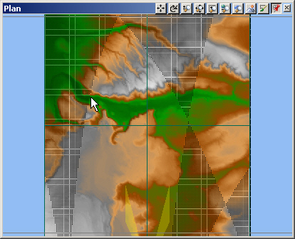
7. Return the Plan Camera to its default location. Uncheck the Terrain Polygon Edges box in the View Preferences window and close it.
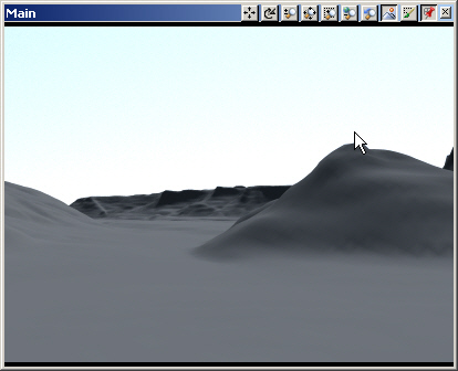
8. Alt-click the Main Camera to activate it and Crtl-click a new location in the drainage about here.
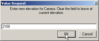
9. Give it an elevation of 2100 meters.
10. Render a preview.
11. Depending on the amount of RAM you have, one of 2 things will happen. VNS will either take some time to think about it and start rendering and or give you a Memory Allocation Failure error.
12. To save time, VNS only renders the DEMs it has to. In this project, our Main camera is only seeing a part of the total terrain. Since we only have 1 DEM, VNS has to make calculations for the entire DEM, which is a big waste of time and memory. The solution is to tile the DEM, that is, subdivide it into several smaller DEMs. VNS will only have to render what the camera sees, resulting in fewer calculations and faster render times. Tiling is done during import for most data types but the gap-filling required by the SDTS DEM format precludes it. SDTS DEMs require a second import to tile the single DEM created by the first import.
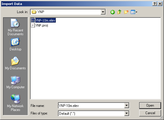
13. Open the Import Wizard . Choose the YNP-10m.elev we just created, and Open it.
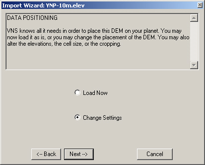
14. Next your way through the Import Wizard to the DATA POSITIONING window. Previously, this is where we accepted defaults and imported. We could do this now and the DEM would be tiled automatically, but we’d like to see what the Wizard is doing. Select Change Settings.
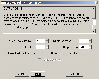
15. Click Next until you get to the OUTPUT DEMS page. The information box at the top explains tiling, telling us the render engine has to load an entire DEM into memory if any portion of the DEM is in camera view. The Import Wizard chooses DEMs Row-Wise and Column-Wise to divide the imported DEM into 300-row by 300-column tiles. That’s where the 7 and 10 come from. We’re not going to change anything so Import.
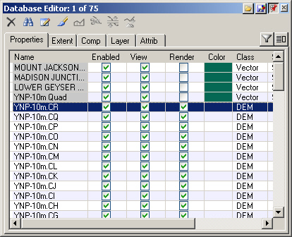
16. If you select an Object in the Database to refresh the list, you’ll notice that we now have 75 objects. That’s 4 quad boundary vectors, 70 tiled DEMs (10 rows times 7 columns), and the original DEM.
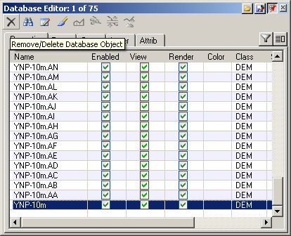
17. Select the original YNP-10m DEM at the bottom of the list. That makes it the active object, so it’s partially highlighted in the Main view where it overlaps matching DEM tiles. If we don’t disable or remove it from the Database, it will still render. Remove the DEM.
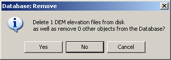
18. When asked if you want to remove the DEM from the disk, answer No; we might want the DEM later on. Save the project.
19. Render another preview. Aside from going much faster, you’ll see from the Status window that we’re only rendering some of our 70 DEMs. The smaller tiles free up valuable memory for other operations, which we’ll need later on.
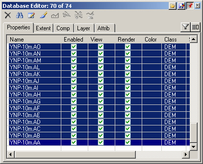
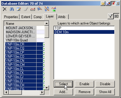
20. Let’s group the 10-meter DEMs on a layer for easy selection. Select the first DEM and shift-click the last one to select all the DEMs. The titlebar will show 70 of 74 objects selected.
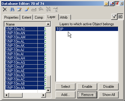
21. Go to the Layer page and Show Properties Panel . You’ll see TOP, which is the default layer VNS creates on import.
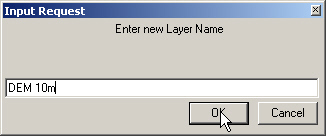
22. Click Add and enter DEM 10m into the Input Request window for the Layer Name. This will add all the 10-meter DEMs to a layer named DEM 10m.
23. To test it, select any object in the list and select the DEM 10m layer. Use the Select button to select all objects on that layer. This may not seem like much help now, but it will be when you have hundreds of database objects.